 |
|
Power DistributionBusbars
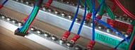
FullPower2 Dual PSU with 1m long busbars Busbars are absolutely the best way to distribute power over large modular systems. They have a resistance of some tens of microohms which is several orders of magnitude better than what can be achieved with printed circuit boards. Unlike other systems, if lower resistance is needed, e.g. for the 0V of a large case, the size of the bars may simply be increased. It is also important to keep the resistance of the supply cables as low as possible (we recommend less than 5 milliohms) because this is where common impedance coupling occurs. Therefore these cables should be as short and heavy as possible and the ideal place for positioning busbars is right in front of the PSU. Conversely, external PSUs with longer cables are non-ideal and will degrade the overall system performance. Multiple PSU systems should have a busbar per rail per PSU, but a single common 0V bar. This may be implemented as one piece or by bolting another busbar between two sets. Busbars may be mounted directly on wooden case sides or bottoms or on insulated blocks on metal 19" rear panels. They can also be integrated with rack frames so that the whole unit may be removed without disconnecting and unscrewing modules. 
FullPower3 Triple PSU and 6U/84HP frame with integral busbars A 430mm/17" bar will fit across an 84HP space and have 36 cable positions, prices from £50 each. Longer bars up to 900mm can be fabricated, or even longer, but the carriage will be higher for lengths over 1m. Module power cables are screwed to the bars with 4mm ring terminals and may have any connector needed at the module end and lengths up to 500mm. KK and other types used for most modular systems are £2-50 each, Eurorack 10-way connectors are £4-75 each and and 16-way £5-75 each. 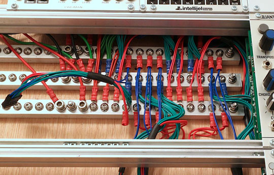
Busbars mounted on skiff base Signal Common and ZeroVolt™In any unbalanced system (and some non-transformer balanced systems) there has to be a common signal reference. Calling this Ground is confusing, so call it Signal Common or Common or simply 0V to differentiate it from other grounds. To keep the 0V voltages in each module at a similar potential the resistance between them has to be very low. With busbar distribution this is limited to the sum of two module cables anywhere in a system. When there are multiple PSUs in a case the Signal Common of each one's distribution should be connected together and the best way is to have a linking busbar between each 0V busbar. This is different to the common practice of connecting power supply commons together, often with a relatively high resistance banana lead. The important difference is which end of the power supplying cables is being used as there will be an undesirable voltage drop along cables carrying higher currents. This principle may be extended for multiple cases and for a fixed studio system the cases may be bolted together and busbars run through the sides or across the back. For portable systems that need to be regularly set up and dismantled for live performance we have a ZeroVolt system. 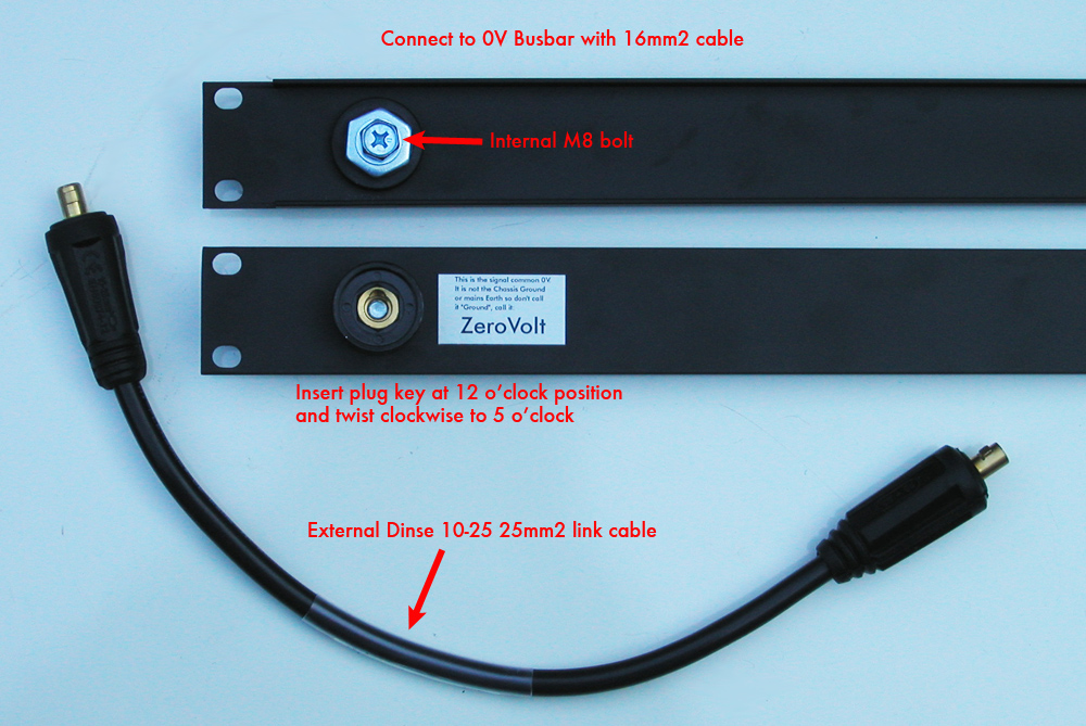
This uses very heavy gauge cables and Dinse connectors to achieve connections of a few milliohms. Each case should have a ZeroVolt socket in the corners adjacent to other cases and these are connected as a grid, not a chain. This is not as good as a direct busbar link, but a good compromise for quickly making connections and still much better than using banana cables. A ZeroVolt connection is typically < 2 milliohms measured busbar to busbar. For very large systems a hybrid solution is possible. A long busbar immediately behind the cases and short cables directly to 0V busbars or to ZeroVolt sockets on each case.  Related Items(Contact us for details.) |