 |
|
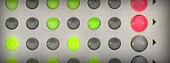
SwitchMix™The Background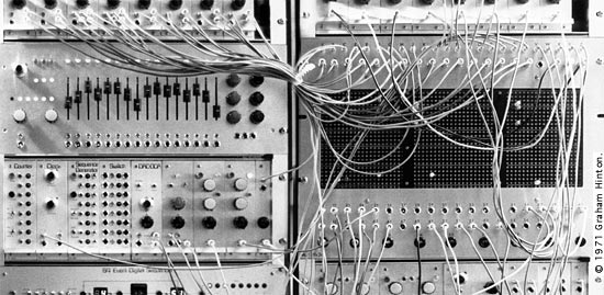 19 rack-mounted prototype ML1000 modular synthesizer system with true summing patch matrix, designed by Graham Hinton, 1971. All modular synthesizer systems are characterised by their patching method—which is often also their Achilles’ Heel. The method chosen dictates how connections are made, and what is possible. Jack patchcords are the most widely used and intuitive, but soon turn into a knitted mess obscuring the panels. They also have other disadvantages: the “standard” 100 k Ω inputs of most modules are too high an impedance for a large system. This results in succeptibility to hum and noise pickup, especially when an output is disconnected and the jack plug handled. Jack plugs also touch the tip to ground as they are being mated or unmated, which momentarily shorts an input or an output depending which end is disconnected. To protect the circuitry a 1 k Ω resistor is normally used in every output, but this gives a 1% loss for every connection—3% if an output is multed to three distinations. Special buffering is required for pitch CVs, and re-tuning is necessary after patch changes. As every connection is point to point, panel jacks have to be provided for multiple mixed inputs—or mixers have to be used—requiring a large amount of panel space and many patch cords for simple basic functions. One alternative was the switch busbars used in the ARP 2500. The busbars allowed fanning out to multiple destinations, but feeding two or more outputs to one busbar averaged the signals instead of adding them. This also necessitated output protection resistors, which caused pitch errors. These systems soon earned a notorious reputation for unreliability due to being open to the air, and the ingress of dirt. The switches also became obsolete. 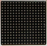 Another more successful system was the Sealectro pin matrix used on EMS synthesizers, but these were not without their problems. The matrix board itself was originally designed to implement diode matrix arrays for programmed control systems, which were obsoleted by the introduction of ROM memories in the mid-1970s, and the use of embedded microprocessors in test equipment. This led to the demise of Sealectro, the main manufacturer of matrix boards. There is now only one supplier of such components—which are both expensive and delicate—and the pins are only available as shorting, or diodes, when what is required is a resistor. 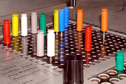 The small matrices used on the VCS3/Synthi A were not designed well; rather, they were a good idea implemented badly, and the large ones on the Synthi 100 were worse, suffering from crosstalk and parallax errors. The outputs were often taken directly from a pot, so the impedance varied with the knob setting, causing further errors, on top of those caused by pin arranging and poor tolerances. To work as expected, a matrix system should not introduce errors when connections are changed, and the outputs should be the true sums of all the inputs. To do that, extra circuitry is required, which was never present in EMS designs—or their imitations. The resistors used in the pins need to be closely matched to ensure tuning accuracy and repeatability. A 1% resistor is within ± 1% of its intended value, meaning there is a 2% maximum spread. 2% error of 5 octaves is 120 cents which means that patching a 5 octave keyboard to two VCOs tuned in unison one end may result in over a semitone difference at the other end. Using 0.1% tolerance resistors reduces the spread to ± 6 cents, which is just slightly out of tune over 5 octaves. Tighter accuracy requires hand matching of components or calibration with trimmers. The ForegroundDespite its shortcomings, the pin matrix system is popular because of its immediacy and compactness. It only requires one operation to make a connection, and it provides visual feedback of a patch. With the resurgence in popularity of modular analogue synthesizers, we are frequently asked, “Why can’t a pin matrix be made?” 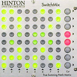 The answer is simple: apart from the considerations above, the basic components are quite expensive making the final cost of a product out of reach of most users. So we rethought the problem. What is needed is the compactness and visual display, but with higher accuracy, and repeatability, at an affordable price. We came up with SwitchMix: a compact matrix of illuminated switches routing through fixed precision resistors, with all the necessary buffering and support circuitry, to make a versatile module in any modular system. Our experience with large matrices in the 1970s taught us several things: firstly, the cost and the problems go up with the area. The larger the size the more redundant crosspoints appear. It may initially seem desirable to have everything connected to everything in one place, but in practise it is better to distribute smaller matrices where they are needed. Secondly, maintenance should be considered. If a large matrix needs repair, your whole system is taken out. Great care has been taken not to use components that would make servicing difficult or impossible. No SMT components are used, and all ICs are socketed. No external connectors are directly mounted on PCBs for ease of replacement. We are happy to discuss your application with you and advise on the best solution. Why no Presets or MIDI Control?SwitchMix™ is an analogue device and is typically used in synthesizer systems with no recall of knob or switch settings or patching. If you need a matrix with preset memories we can build one and have done so in the past. It will cost more, be larger and the specification, although good, will not be quite as good as SwitchMix™. No means of control, even a relay, will get close to the performance of a good quality simple switch. |