|
A Guide to EMS
VCS3 and Synthi A/AKS
Modifications and Servicing
Miscellany
The KS Sequencer
The Touch Keyboard Sequencer used in the AKS is no longer supported by EMS.
There are two main problem areas with this design, the inputs and the memories.
The circuitry was designed around the original standard 7400 series TTL and the memories are MOS shift registers, both have a much higher current draw than modern equivalents.
The touch sensors are dependent on an undocumented feature of TTL gate inputs and does not work with all makes (thanks, David!) so only replace with the same type of chip.
Other TTL ICs could be replaced with the 74LS, 74HC or 74HCT equivalent. If it follows a standard TTL IC use HCT to get the logic thresholds correct.
Here is a redrawn schematic to aid in repair.
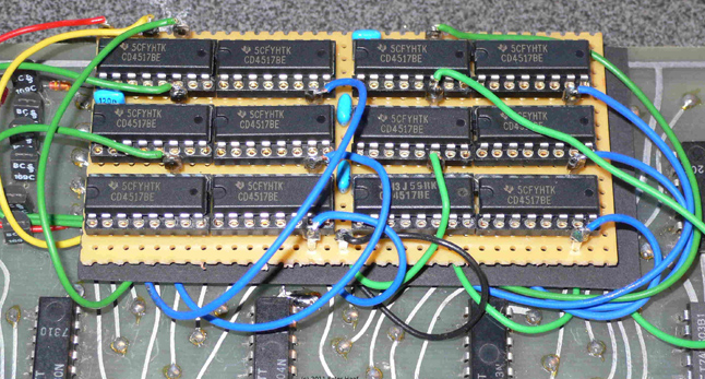
The MOS shift register memories are easily damaged by static and have been unavailable for decades.
Recently Peter Haaf in Germany repaired his KS with a substituted CMOS memory:
Hi/Lo Range Switchable Oscillators
As standard, Oscillators 1 and 2 were meant to be tracking audio generators and Oscillator 3 an LFO. As the circuitry is almost identical Oscillator 3 may be converted to be the same as Oscillator 2 or all three may be made range switchable.
Ideally, each Oscillator should have the two capacitors on the pcb joined at the current input end, to keep this sensitive point a short path.
Fly a screened twisted pair cable wired to the other end of each capacitor to a panel switch such that it switches the larger capacitor in parallel.
Ground the screen from a nearby panel control.
Oscillator 3 does not include the 100R preset to adjust the exponential law tracking, but this may be added by inspecting the pcb differences between Oscillators 2 and 3.
If the V/octave adjustment is done elsewhere in another modification then it not necessary.
Here is a recent modification of all three oscillators for high/low ranges and sync:
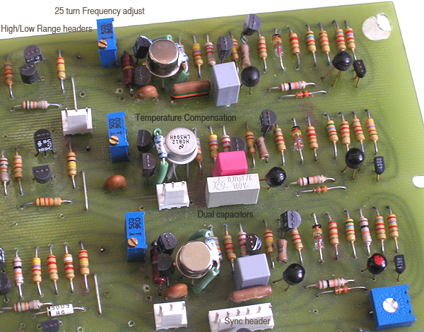
In this case the 100R trimmers have been removed and a 25 turn trimmer used on another pcb supplying the pitch CVs.
Molex KK 0.1" headers have been used for the connections to the range switches and sync pots so that the board is removable.
A row of 1mm holes was drilled on 0.1" spacing in suitable places and wired on the solder side.
By placing them next to a 0V trace tinned solid copper wires were soldered between the trace and connector pins to hold it in place and provide a screen for the cable.
Foot Pedal Controller Input
The High Level Inputs may be converted to take foot pedal controller inputs.
In the early days of analogue synthesizers foot pedals used to have a mono jack and appeared as a resistance that varied from 0 to 10k ohms.
Since the advent of digital synthesizers, pedal controllers have have stereo jack plugs and appear like either a 50k or a 20k pot.
This circuit will accept both types, but the weak pullup resistor may have to be adjusted for the type used to get the required range.
When driven from a low impedance source this resistor will have negligible effect.
Replace the mono jack with a stereo jack with break contacts and wire as shown.
The 47k resistor and 2.5µ capacitor are already mounted on the connectors and may be mounted on the DPDT switch.
If the high gain and an EMS keyboard are not being used this circuit may be simplified.
The Input Amplifier is a discrete transistor op amp with a gain of x2 or x200, or x1 with the 100k resistors in the keyboard umbilical cable.
By changing the input resistor on the circuit board the pullup may be mounted there too making it easier to find +12V.
It was not a very good mic amp anyway, having maximum gain and post attenuation instead of variable gain.
Inverter Pin
If you can spare a patch pin one may be modified into this patchable inverter.
The resistor has to be removed from the pin and a hole drilled through the top of the cap.
A length of sub-miniature screened cable is fitted to the pin, the trickiest part is getting the inner core inside the pin tube without melting the insulation.
Thread the cable through a pin storage hole to this circuit inside:
NOTE: VCS3s and Synthi As have reversed patch matrixes, the diagram is shown for a VCS3 which has matrix inputs to pin tip.
For a Synthi A reverse the connections so that matrix output goes to pin tip.
Inserting the pin at any matrix position will allow that connection to be adjusted between the normal signal and its inverse.
The pot may be omitted if only a simple inverter is required.
Key Indicator
The lamp on the Envelope Generator was always a bit cheap and nasty.
As it is a filament bulb which takes time to turn on it sits barely on and then sluggishly brights up when the envelope is on.
The lamp may be replaced by the following circuit, wired between the Attack and Decay pots:
As LEDs were not available when the VCS3 was designed a "Gerry Anderson" style lens looks suitably contemporary.
Farnell part number 121-8551 is a drop in replacement.
The resistor and zener may be mounted directly on its solder tags.
|