by Graham Hinton
Last updated: 23rd September 2005
Also check the Special Sales Items for unrepeatable synthesizer related offers.
So you've just picked up a VCS3 or Synthi A in mint condition and are feeling pleased with yourself? Well, this may be a plus for a "collector", but it is a definite minus if you actually want to use it. Nobody that was ever really serious about these instruments left them unmodified, a fact completely ignored by all the hacks who have written retrospective appraisals of EMS equipment recently.
Even in its day, this is what W.Carlos wrote in the Whole Earth Catalogue:
"The PUTNEY is a real toy. Its components are highly unstable/unpredictable and the selection made is highly gimmick orientated and does not by any stretch of the mind permit any subtle sounds & exp. to be constructed. It also has a so-called touch-sensitive keyboard which has to be tried to be believed, it's that awful. No feel or physical feedback at all (as there is in a piano, for example); again, another great concept worked out in ignorance (and the one I tried worked backwards: softer touch = louder sounds!) But it is small & portable & groups might like it for special effects."
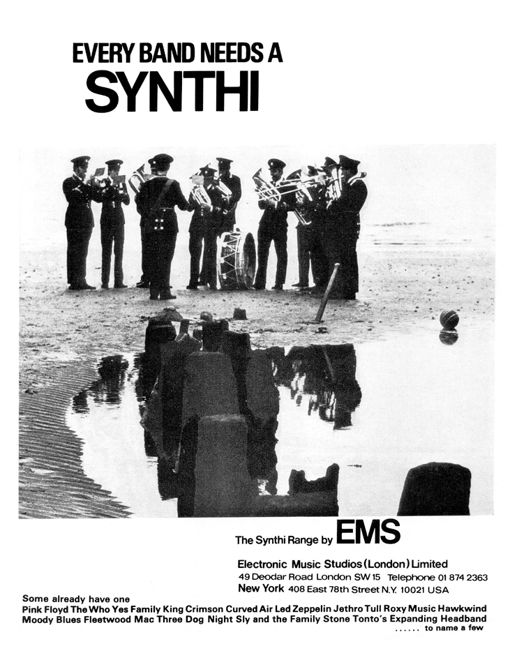
This would have been fair comment, but coming from somebody who had a completely non-standard customised synthesizer and a close relationship with the Moog company it transcended hypocrisy into plain bitchiness as well as missing the point.
There are quite a few simple improvements which can be made that will completely transform the operation and performance of these classic synthesizers:
All of these modifications can be expertly performed by Robin Wood at EMS. Please note that Hinton Instruments is a separate company and does not repair synthesizers or disclose EMS information for clone builders. This information is presented for those EMS owners who may be put off by the risk or cost of shipping their precious posession or who prefer to do the modifications themselves.
Most of the circuitry is contained on three separate printed circuit boards which are loomed to the panel mounted controls. This leaves plenty of room for adding extra knobs, switches and component boards, although there is less room available inside a Synthi A than a VCS3. Looking in from the back there are three boards: A, B & C held in by a single screw at the top.
The main change during the lifetime of the VCS3 and Synthi A was with the introduction of the KS sequencer when the power supply was uprated to provide extra power to the 8-way Keyboard socket. The original VCS3 (Putney) had the early power supply and the Synthi VSC3 II and the Synthi AKS had the later.
Although these modifications are quite simple they should only be performed by those experienced in electronics with access to a good oscilloscope and frequency meter. Do not attempt otherwise.
One of three similarly modified AKS used by Britain's first all synthesizer band Zorch since 1972. This one is probably the most modified and widely gigged Synthi A and is still in regular use, the whereabouts of the other two are unknown.
Each VCO is about an inch wide strip vertically down Board C with a similar layout.
VCO3 is in the middle, note the larger capacitor.
The two transistors glued together with epoxy adhesive (not noted for thermal
conduction) require replacement with an LM194/LM394 dual supermatch NPN pair
for close thermal balancing and better exponential conversion.
Check the pinout with the data sheet.
Remove the three transistor pairs glued together with epoxy adhesive just above the presets about half way up Board C with an LM194/LM394. The metal can version is required as the plastic DIL package is difficult to mount. The pins are in a different order and the TO-5 can should be orientated with the tab towards the board edge connector and the middle legs should be sleeved and twisted to be at the tab end i.e. swap the bases and collectors. Emitters at top, collectors in the middle and bases at the bottom (tab end).
Replace board C and check that the Oscillators are still functioning before proceeding with the other modifications.
Replace the 1k0 (Brown/Black/Red) resistor at the anti-log summing junction to ground with a Tel Labs Q81 TC resistor of the same value. This is a special wirewound resistor with a Temperature Coefficient equal and opposite to that of a silicon transistor Base-Emitter junction so that changes with temperature may be cancelled out. It was originally specified in AN-30 by National Semiconductor and was commonly used in most analogue synthesizers, but may now be unobtainable. There are some modern equivalents listed below.
The resistors are half way up board C below and to the right of the presets for each oscillator and are normally slightly larger metal oxide types rather than carbon film, at least for VCO1 and VCO2. Trace the track back to one LM394 base to be sure. This mod should be done with the dual transistor and ideally the Q81 should be in thermal contact with the can, but you will probably just have to loop the leads to make it fit the smaller spacing.
Replace these components on Board C:
The poor quality carbon presets may be replaced with cermet equivalents or even sealed multiturn cermet types for better tuning resolution. The latter would require fixing in place with an epoxy adhesive and wiring as the pinouts are not the same.
The standard Oscillator frequency controls are really cheap, tacky Japanese slow motion vernier drives with an ordinary carbon pot behind. Apart from looking trash the backlash is awful and this directly effects the tuning, there is no point in improving the electronics and leaving these controls to ruin it.
Replace the pots with ten turn wirewound types. I always used a Beckman Model 7246 10k ten turn wirewound type for smooth action and because the wiper stays on the wire. Other models and makes may leave the element while turning (to reduce wear) so buy one first to check the action and feel. NOTE the pin order the wiper is often at the end - if you get it wrong you will connect the power rails across the wiper and one end and melt the wire! You will need to make an aluminium panel to go behind the Oscillator frequency controls as the slow motion knobs have a larger mounting hole size.
The Beckman ten turn DUODIAL (46mm diameter) is contemporary and looks in keeping, Spectrol make a similar one, but not quite as classy. They may be called 15 turn types, but the pot prevents more than ten rotations. The input resistors may need to be increased by 150% because the slow motion pots only use 180 of the 270 degrees of pot rotation. This may be adjusted to taste: 1 octave per rotation or 10 semitones per rotation.
![]()
The standard patchpins contain 2k7 5% resistors and the red "precision" pins
contain 2% resistors. 1%, 0.5% and 0.1% resistors are easily obtainable these
days and as the resistor errors effect patch repeatability and tracking it is
best to replace them.
N.B. Synthi 100 patchpins contain 10k resistors so don't get them mixed!
There are at least two designs of pin which are assembled differently. Some the cap unscrews, others you have to pop it off carefully with pliers. One has a solid pin and a solder cup inside, the other has a hollow pin. It's worth checking for solder dry joints and that it was not made correctly i.e. soldered at the top if it's the tube type.
The correct way to solder a component in the pin is to take one lead right through the pin and solder it at the tip, like an RCA Phono jack (you do know how to solder those don't you?). Trim the projecting lead and then solder the other lead at the top of the carrier frame. On the solid types, solder to the bucket first.
If your pins look black give them a twist in a rag dampened with contact cleaning fluid.
EMS Sync is far more tonally versatile than any other analogue synthesizer commercially available. There are two ways of implementing this feature:
Each sync circuit comprises a single pole centre off switch to select the other two oscillator outputs (taken from the top of a level pot), this is taken to an extra pot and the wiper feeds a resistor connected to the Oscillator hysteretic switch to alter its threshold. This has to be "flown" onto the pcb and soldered to the end of the 22k resistor as indicated. The pcb layout of each Oscillator is identical at the top of the board.
VCS3: Mount the Sync level pots (3/8" hole) between the oscillator shape and
level pots on a centre between the tops of the "5 lines". The centre off switch
(1/4" hole) is then 18mm above that.
Synthi A: the best position is to the far right of the Oscillator panels.
After doing the all these modifications to a VCS3 all three Oscillators stayed
beating for an 8 day test with a maximum absolute drift of 10 cents with the
temperature being cycled from -5 to +30 degrees Centigrade.
Who says analogue synthesizers go out of tune?
If you are experiencing intermittent pin contacts the matrix patchboard may require cleaning, but first check the state of the pins. If the pins are discoloured give them a wipe with a contact cleaning fluid to restore to a bright tin finish. If the pins have a sticky coating the pin retainer needs replacing. The pin holder is simply a counter drilled block of wood behind the panel with a friction layer to hold the pin tip.This layer varies from a plastic foam that invariably decomposes with age to rubber matting or even a piece of carpet [sic.].
Modern high density packing foam (such as that supplied with bare hard disk drives) has been found to be suitable. Clean off the remains of the old strip so that it cannot get on the pins and then glue a strip of foam cut to size to the wood. Ensure that the adhesive is set and inert before inserting the pins!
If the patch board itself has been damaged by atmospheric corrosion or the entry of foreign bodies it's time to open up the matrix. This is much less daunting than it sounds, but great care should be taken as these are extremely expensive to replace. The matrix assembly is held together by twelve bolts with Nyloc nuts which should be removed with a 6BA nutspinner. The eight corner bolts go through the black Traffolyte top although the bolt heads do not go through the front panel. The four middle bolts do not go through the Traffolyte so may spin when undoing the nuts - to prevent this just press down on the back of the matrix to pinch the bolt.
With the nuts and washers removed the back simply lifts off with the row contacts leaving the column contacts in place. Inspect the contacts for mechanical and chemical damage. Bent contacts may be carefully repositioned with pliers and they may be cleaned with a cotton swab and contact cleaning fluid. Remove all dust and debris. When reassembling be extremely careful not to overtighten the nuts. The matrix is constructed from srbp laminate which shatters very easily!
The Envelope Generator Trapezoid normally goes negative when on and positive when off and so confuses the naive user brought up on preset synthesizers. This is easily altered with the following circuit mounted on the Level pot:
Make all 4 resistors the same value, eg 33k; this just saves having to get two resistors of exactly double values, it will work with whatever you have handy. When the switch is at ground you have a normal inverter configuration: gain = -1; when the switch is connected to the pot wiper the gain = -1 + 2 = +1.
One way of implementing this is to mount the circuit on a small piece of prototype board on a pcb mounting pot. Replace the existing pot with this assembly and tap the power supply from a nearby pot - Decay has +12V & -9v across it.
The circuitry driving the matrix is not low impedance, often it is directly off the level pot wiper (!) which means that as you add pins or change output levels any existing settings are altered and interact, this is especially annoying with tuning.
This is easily overcome by buffering all the drives to the matrix board with op amp voltage followers (4 quad op amps required). A much better, but more complex solution is shown below:
This also achieves True Summing of the patchboard (the standard circuit is a weighted average). The circuitry may be built using quad op amps and mounted close to the matrix patchboard. The IC driving the matrix must be capable of operating into the load of several pins in parallel without becoming unstable. The power supply may be taken from the nearest convenient point, don't forget some decoupling capacitors across each rail.
The 2k7 resistor shown is equivalent to one patchpin. It may be omitted if the corresponding changes are made to the receiving circuits. For better tracking of the Oscillators replace R179, R212 and R246 on Board C with 18k 1% (or better) resistors.
N.B. the patchpin resistors should be altered to at least 10k (higher values may crosstalk more). The signals are now inverted on the patchboard, but the two inversions cancel. This should be noted if connecting directly to the patchboard.
All sixteen inputs and all sixteen outputs plus a few grounds and anything else you fancy may be taken to a multiway connector e.g. 37-way D-type mounted on the rear panel - there's room above the input jacks. Then you can either make a multiway to a box breaking out to jacks (like a stage box) or to another unit incorporating more processing circuitry. At least the Control Voltage processors similar to an ARP2600 would be extremely useful. If you do it this way the front panels will still look tidy. You could use a 50 way D-type or 57-series (like those used for SCSI-1) instead for more expansion e.g. more inputs, VC shape,etc. Ribbon cable is not recommended for external connections.
The Oscillator Shape pots just provide a control voltage and this is easily altered to allow for another source. Add a 3.5mm jack socket or similar connector at a convenient place on the panel and mix the socket and the pot wiper with two resistors.
This same technique can also be applied to Filter Response if required.
As standard, Oscillators 1 and 2 were meant to be tracking audio generators and Oscillator 3 an LFO. As the circuitry is almost identical Oscillator 3 may be converted to be the same as Oscillator 2 or all three may be made range switchable.
Remove the 1 microFarad capacitor from Oscillator 3 and replace with a 15nF capacitor like the other two Oscillators. Fly a screened twisted pair cable wired to each capacitor terminal to a panel switch with the larger capacitor mounted on it such that it switches in parallel. Ground the screen from another panel control.
Oscillator 3 does not include the 100R preset to adjust the exponential law tracking, but this may be added by inspecting the pcb differences between Oscillators 2 and 3.
The normal route for external pitch control is from the 8-way Jones socket via the Input Channel amplifiers which effect the tuning range. Sometimes 10-turn pots were used on the Input Level controls for easier tuning, but this made it awkward for level control.
It is better to add an op amp with multiturn presets feeding each VCO directly or via the matrix switched between Input Channel 1, then you can calibrate and track external 1V/octave CVs. The low-level microphone jack sockets may be reassigned as Control Voltage and Gate Inputs. If low-level inputs are still required the high-level inputs could be made switchable. The normal pitch characteristic was 0.32V/octave which has led to rumours of incapatibility with 1V/octave synthesizers. This is untrue, it is only necessary to scale down the control voltage by about a factor of three.
Although the Trigger Key is specified as being a +4V voltage it should really be a switch to +4V, here's a simple interface circuit that will accept external +10V Gates or LFO waveforms and still function with EMS keyboards:
This circuit will trigger the Envelope Shaper from any external voltage sufficient to turn the NPN transistor on (i.e. >1V) and will protect from gates exceeding the power rails.
WARNING: Improper Key interfacing may cause cycling or incorrect voltage output levels of the Envelope Shaper and may even damage it.
Replace the toggle switches with better quality ones (C&K), if you have those grey plastic ones with a black plastic toggle and a sloppy action.
Replace the sharp edged cheap plastic knobs with Elma collet knobs.
Both Bourns and Spectrol now make affordable conductive plastic pots. After you feel the difference to the gritty standard ones you'll probably want to replace the lot! If you have buffered the patchboard they can all be 10k, rather than 5k which was just to try to make the output impedance low.
Replace the stiff Attack button with a V3 microswitch and panel actuator.
Put an IEC inlet on the mains and XLR connectors on the outputs, you could even add a proper balanced output amplifier too.
Most VCS3/Synthi A problems are caused by Board A especially the Power Supply Regulator which is not exactly the finest circuit ever designed. Often a failed power supply can be fixed by resoldering the large components at the top of the board - look for the tell tale burn marks. If this fails it is better to completely replace the whole power supply with a modern +12V/-9V design based on 7812/7909 or LM317/LM337 voltage regulators. The stability of the whole instrument depends on the integrity of the power supply so it's not worth skimping on this one.
If you can find a psu module that fits the bill and the available space then use it. Try to find a LINEAR one or at least one intended for analogue applications. Most small PSUs are switch-mode theses days and are intended for PCs and if they have a -ve rail it does not normally provide very much current. I would not recommend putting one of these close to the matrix patchboard.
On the older models there is a separate +11V rail for the internal power and reverb amplifiers. The best policy it to remove the regulator components from Board A except Q1 and then wire +12V and -9V from the replacement PSU to a convenient point. The transformer, bridge rectifier and reserviour electrolytics are mounted in the base of a VCS3 - upgrade them too.
The electrolytic capacitors in the 60/70s were normally reckoned to have a working life of 10 years - so you've been living on borrowed time for the past 15 years! The construction is two sheets of aluminium foil with an electrolytic paste smeared on them rolled up, like a Swiss roll cake. Eventually the paste corrodes the aluminium and the component fails. If you ever have the misfortune to be in the same room as a big one when it explodes it's rather like being trapped inside one of those snowstorm souvenir novelties!
As soon as one fails it would be a good insurance policy to just replace all the electrolytics with modern hi-grade components in one go. Otherwise you might be fixing them one at a time for the next n-years.
In some models the power loom wiring is too small and causes voltage drops. Replace the Orange and Blue 7/0.2 wiring between Board A and Boards B and C with 16/0.2 size.
The ICs used in the Mk I version for the internal squeakers and reverb drive are no longer obtainable. If they fail, it's time to completely replace Board A. Rebuild the equivalent circuitry on an extended (220mm) Single Eurocard.
The original Bulgin 3A circular connectors used for the mains inlet are still obtainable, BUT these are and always were crapp. These connectors are no longer considered safe for mains voltages and have been derated to 50Vac maximum. The socket on the mains cord in particular is liable to break and expose live mains wires. The best solution is to remove the mains inlet and file out the hole to take a modern IEC-22 6A inlet. Any moulded cordset can then be used with complete safety.
Those idiots who believe that not having the original connector will somehow change the sound are welcome to get themselves electrocuted by buying the Bulgin parts from Farnell InOne:
Users with more sense will do this:
These are redrawn from the originals and are in .gif format:
| Part | Farnell Order Code | RS Order Code | UK Price £GB | Notes |
| TO-5 Supermatch pair | LM394CH | n/a | £3-82 | Metal Can not DIL |
| 2k7 0.1% Resistor | 339-593 | 166-122 | £0-80 | for Patchpins |
| 10k0 0.1% Resistor | 340-133 | 166-728 | £0-80 | |
| Sealed Cermet Trimmer 100R | 348-818 | 154-2173 | £0-97 | 25 turn |
| Sealed Cermet Trimmer 100k | 348-909 | 154-2274 | £0-97 | 25 turn |
| Bourns 5k Lin Pot | 148-575 | £3-06 | Conductive Plastic | |
| Bourns 10k Lin Pot | 148-576 | 173-631 | £3-06 | Conductive Plastic |
| Bourns 10k Log Pot | 109-085 | 173-697 | £3-48 | Conductive Plastic |
| 15-turn 46mm Dial (Beckman) | n/a | 509-428 | £12-28 | Classy |
| 15 turn 46mm Dial (Spectrol) | 146-835 | 107-3138 | £11-11 | 2nd best |
| C&K 7103SYZBE SPDT-c/o | 151-167 | 330-979 | £2-00 | for Sync select |
| C&K 7101SYZBE SPDT | 151-165 | 330-963 | £1-97 | replacement |
| Elma 14.5mm collet knob | 320-651 | 499-488 | £1-64 | for Sync level |
| Elma 14.5mm cap - red | 320-869 | n/a | £0-188 | packet of 5 |
| Elma 14.5mm cap - black | 320-845 | 499-517 | £0-188 | packet of 5 |
| Elma 21mm collet knob | 320-699 | 499-589 | £1-88 | facelift |
| Elma 21mm cap | 320-900 | 499-602 | £0-216 | Black, FEC have Grey, Red & Green |
| Red Button Actuator | 337-908 | £3-27 | for V3 microswitch | |
| Bourns 534 20k 3watt, ten turn wirewound | 351-805 | £4-89 | suggested * |
* Several 10 turn pots types are available. The Bourns 534 series seems to keep the wiper on the track as it turns and feels ok. Check other types carefully.
A 1k resistor with a positive temperature coefficient of 0.3% or 3300ppm per °C is required.
These are as rare as rocking horse droppings, but try:
Prices may vary, sometimes significantly, between distributors so these are only a guide - check when ordering.
Farnell Electronic Components Ltd.
RS Components
Go to EMS Main Page
Go to Hinton Instruments' Web Page
Synthi is a trademark of Electronic Music Studios.
All manufacturers' trademarks are acknowledged.