EMS Sync is far more tonally versatile than any other analogue synthesizer commercially available.
There are two ways of implementing this feature:
OSC Sync - fixed strength, omit the pot and make R1 10k - 100k to suit.
OSC Sync - variable via pot
Each sync circuit comprises a single pole centre off switch to select the other two oscillator outputs (taken from the top of a level pot), this is taken to an extra pot and the wiper feeds a resistor connected to the Oscillator hysteretic switch to alter its threshold.
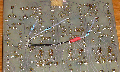
This has to be "flown" onto the pcb and soldered to the end of the 22k resistor as indicated.
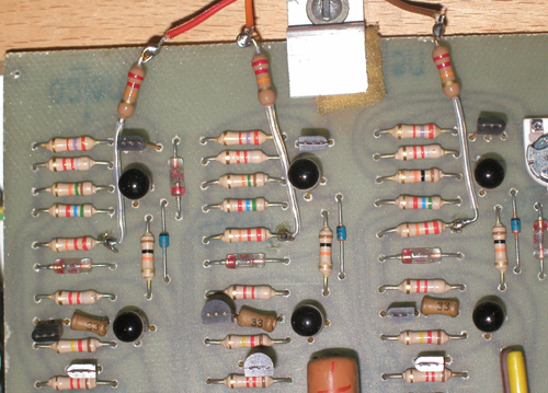
The pcb layout of each Oscillator is identical at the top of the board.
The resistors may be simply attached to the top of the pcb:
A better method is to use a connector so that the board may still be removed.
First drill a row of six 1mm holes 0.1" apart in an empty part of the board by a 0V track.
Then fit a Molex 6 way KK header, a right angle type bent straight will give extra length on the reverse to bend over and solder to the 0V track.
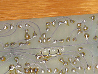
The 22k resistors may then be attached to the solder side of the board as shown:
A loom can be made from the pots to a Molex 6 way housing using single core screened cable.
Note that the pot 0V is provided by the cable screen rather than taken from another panel control.
VCS3: Mount the Sync level pots (3/8" hole) between the oscillator shape and level pots on a centre between the tops of the "5 lines".
The centre off switch (1/4" hole) is then 18mm above that.
Synthi A: the best position is to the far right of the Oscillator panels.
The circuitry driving the matrix is not low impedance, often it is directly off the level pot wiper (!)
which means that as you add pins or change output levels any existing settings are altered and interact, this is especially annoying with tuning.
This is easily overcome by buffering all the drives to the matrix board with op amp voltage followers (4 quad op amps required).
This will prevent loading dropping the voltages, but not stop interaction due to the various input impedances.
A much better, but more complex solution is shown below:
This also achieves True Summing of the patchboard (the standard circuit is a weighted average) so that musical intervals will add correctly.
The circuitry may be built using quad op amps and mounted close to the matrix patchboard.
The IC driving the matrix must be capable of operating into the load of several pins in parallel without becoming unstable.
The power supply may be taken from the nearest convenient point, don't forget some decoupling capacitors across each rail.
The 2k7 resistor shown is equivalent to one patchpin.
It may be omitted if the corresponding changes are made to the receiving circuits.
For better tracking of the Oscillators replace R179, R212 and R246 on Board C with 18k 1% (or better) resistors.
N.B. the patchpin resistors should be altered to at least 10k (higher values may crosstalk more).
The signals are now inverted on the patchboard, but the two inversions cancel.
This should be noted if connecting directly to the patchboard.
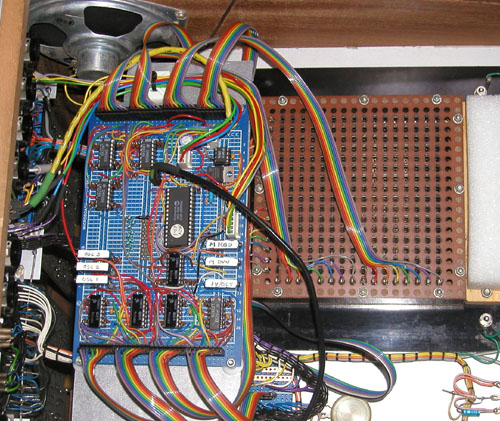
This is a fairly difficult modification to implement, the prototype took me about two weeks to build and it requires disconnecting the matrix completely.
For a tidier solution we have designed a pcb incorporating some of the other modifications that fitted directly on the matrix,
but VCS3 and Synthi A matrix boards have different orientations.
We are planning producing a limited run of an updated version of this board for VCS3 only and if you are interested please Contact us.
It is still possible to modify a Synthi A, despite the limited space, as done here by Peter Haaf:
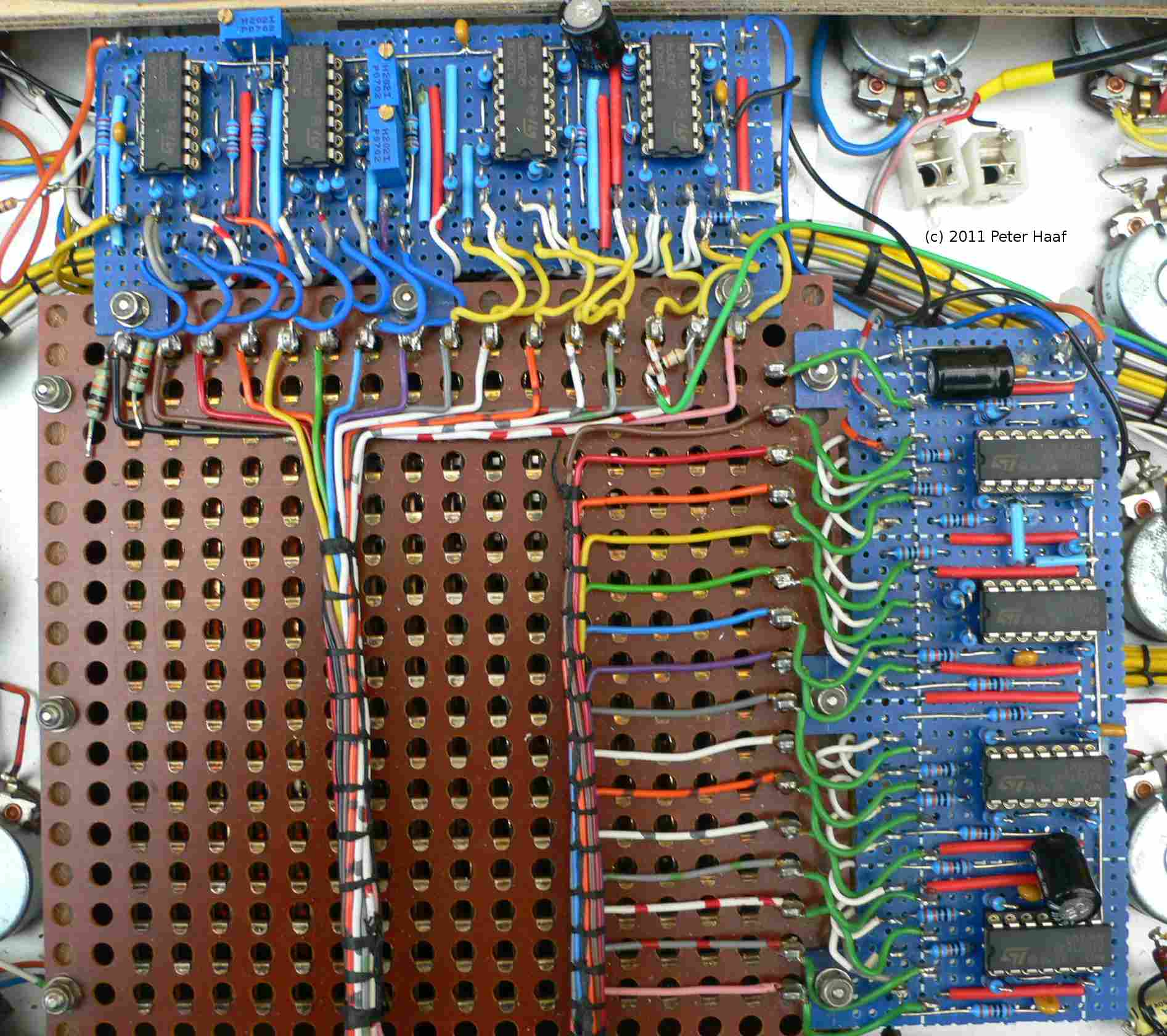
Note that the matrix is rotated 90 degrees from the VCS3, effectively reversing the tip and sleeve of the pins.
For a modern take on True Summing Matrix Patching please see our PinMix™ and SwitchMix™.
1V/Octave and Gate CVs
The normal route for external pitch control is from the 8-way Jones socket via the Input Channel amplifiers which effect the tuning range.
Sometimes 10-turn pots were used on the Input Level controls for easier tuning, but this made it awkward for level control.
It is better to add an op amp with multiturn presets feeding each VCO directly or via the matrix switched between Input Channel 1,
then you can calibrate and track external 1V/octave CVs.
The low-level microphone jack sockets may be reassigned as Control Voltage and Gate Inputs.
If low-level inputs are still required the high-level inputs could be made switchable.
The normal pitch characteristic was 0.32V/octave which has led to rumours of incompatibility with 1V/octave synthesizers.
This is untrue, it is only necessary to scale down the control voltage by about a factor of three.
Although the Trigger Key is specified as being a +4V voltage it should really be a switch to +4V, here's a simple interface circuit that will accept external +10V Gates or LFO waveforms and still function with EMS keyboards:
This circuit will trigger the Envelope Shaper from any external voltage sufficient to turn the NPN transistor on (i.e. >1V) and will protect from gates exceeding the power rails.
WARNING: Improper Key interfacing may cause cycling or incorrect voltage output levels of the Envelope Shaper and may even damage the FET which is a specially selected part no longer available.
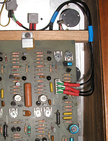
If you are using Silent Way or Volta with a dc coupled balanced audio interface you will get better results by having balanced inputs and using TRS-TRS jack cables.
Replace the mono jacks used for CV and Gate with stereo jacks.
When used with mono jack plugs there will be no difference and the 1V/oct preset should be calibrated for this usage.
With a balanced output and TRS cables double the range will be achieved.
(The XCV inputs may need to be swapped, depending on other modifications, to get the polarity correct.)
N.B. The calibration routines for this software is really calibrating the audio output to 1V/octave, but it has the effect of correcting an Oscillator's tracking errors as it is in the loop.
When driving multiple Oscillators it is assumed that they tracked to begin with, otherwise separate channels will need to be used.
Trapezoid Polarity Control
The Envelope Generator Trapezoid normally goes negative when on and positive when off and so confuses the naive user brought up on preset synthesizers.
This is easily altered with the following circuit, now called an "attenuverter", mounted on the Level pot:
However, like attenuverters, it has the disadvantage of an indistinct centre off position and reduced resolution.
By adding a switch the polarity may be inverted keeping the full pot resolution:
Make all 4 resistors the same value, e.g. 33k; this just saves having to get two resistors of exactly double values, it will work with whatever you have handy.
When the switch is at ground you have a normal inverter configuration: gain = -1; when the switch is connected to the pot wiper the gain = -1 + 2 = +1.
One way of implementing this is to mount the circuit on a small piece of prototype board on a pcb mounting pot.
Replace the existing pot with this assembly and tap the power supply from a nearby pot - the Decay pot has +12V & -9v across it.