A Guide to EMS
VCS3 and Synthi A/AKS
Modifications and Servicing
Essential Modifications
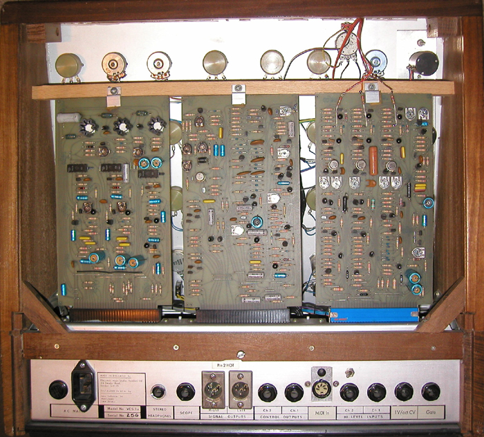
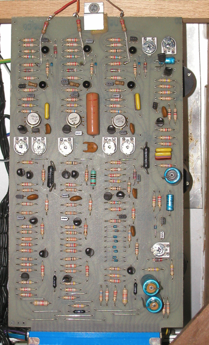
There are three printed circuit boards inside a VCS3 or Synthi A, viewed left to right:
Board A: PSU Regulator, Output Amplifiers and Reverb.
Board B: Ring Modulator, Filter, Envelope Shaper and Input Amplifiers.
Board C: Oscillators, Noise and Meter.
Board A was changed on the Synthi VCS3 MkII and Synthi AKS to have a heavier duty power supply and different output amplifiers.
It is easy to identify by having a small connector at the top going to a heatsink.
The most important modification is to stabilise the three Oscillators on Board C.
Temperature Balancing
Temperature balancing keeps the two transistors in the exponential converter closely matched and thus prevents drifting as the internal temperature changes due to different currents through the transistors over the working range.
This is different from compensating for errors caused by the external ambient temperature, see below. Both modifications need to be done.
Each VCO is about an inch wide strip vertically down Board C with a similar layout. VCO3 is in the middle, note the larger capacitor.
There have been several several versions of Board C with minor differences. Some used 2C746 or 2N2916 dual transistors in metal cans, in which case no change is necessary.
If two transistors glued together with epoxy adhesive (not noted for thermal conduction) are used these require replacement with a metal can dual transistor.
We used to use a LM194H/LM394H dual supermatch NPN pair for close thermal balancing and better exponential conversion, but these are no longer in made by Texas Instruments/National Semiconductor.
A replacement AS194H/AS394H is now being made by Alfa RS. in Latvia
Other devices that could be substituted are the Analog Devices MAT02 (which is also obsolete) or its replacement the MAT12AHZ. Both of these are in TO-78 metal cans whereas most other dual transistors are in DIL or SMD packages.
It is important to use a monolithic dual transistor for close thermal coupling, rather than two matched chips packaged together.
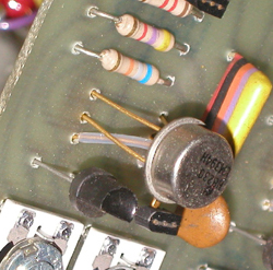
Identify and desolder the three transistor pairs glued together with epoxy adhesive just above the preset trimmers about half way up Board C and replace with a dual transistor.
The pins of most dual transistors are in ebc order and the TO-5 can should be orientated with the tab towards the board edge connector.
The discrete transistors are in ecb order so the middle legs of the replacement should be sleeved
and twisted to be at the tab end i.e. swap the bases and collectors. Emitters at top, collectors in the middle and bases at the bottom (tab end).
If you cannot find proper sleeving a short length of stripped wire insulation will suffice.
If the holes in the pcb are in a straight line the leads need to be swapped.
If the middle holes are further out or the discrete transistors are already swapped, they don't.
If in doubt follow the traces.
Replace Board C and check that the Oscillators are still functioning before proceeding with the other modifications.
Temperature Compensation
Silicon transistors used in exponential convertors have a temperature coefficient of -0.003354/degree C at 25 degrees C.
(To demystify, this is simply the ratio of a 1 degree C change to the temperature above Absolute Zero.)
To compensate for this change a resistor with the opposite coefficient is used to increase the voltage at the base of the transistor.
Special wirewound resistors known as Q81s were manufactured by Tel Labs for this purpose and were used in many analogue synthesizers in the early 1970s, but these are no longer manufactured.
Beware that tolerances are often given as the resistance tolerance when the most important parameter is that the temperature coefficient tolerance should be less than 0.5%, but this varies with every batch over a 10% range.
There is a lot of misinformation about what temperature coefficient is required.
The TC resistor forms part of a potential divider with a 12k input resistor plus a 2.7k pin resistor so the coefficient is altered.
The correct resistor to use should be a 1k ±1% wirewound type with a +3500ppm ±1% @ 25 deg C temperature coefficient.
When part of a 15k + 1k potential divider this will be very close to the desired 3354ppm.
Buy three resistors together so that they are from the same batch of wire and have exactly the same error.
The best devices to use now are PT1000 thin film RTDs (RS part number 362-9913) with a 3850ppm TC and which have to be glued to the top of dual can transistor.
Note that in the oscillator circuit the front panel pot and internal trimmer are summed with the CV each through a different resistor value which gives each a different temperature coefficient! The best way is to sum all CVs first to 0.144V/oct and then go in with a single resistor, in this case 7k5 1%.
Oscillators 1 and 2 have a 100R trimmer in series with this resistor to adjust the exponential law so this effects the temperature coefficient too. Oscillator 3 does not have a trimmer.
This schematic shows the front end of Oscillator 1, the other two are similar.
Q59 and Q60 are the exponential transistors to be replaced by a monolithic pair.
R176 is the Vbe summing resistor to be replaced by a PTC type and PR16 is the V/oct adjustment.
Replace the 1k0 (Brown/Black/Red) resistor at the anti-log summing junction to ground with a TC resistor of the same value.
The resistors are half way up board C below and to the right of the presets for each oscillator and are normally slightly larger metal oxide types rather than carbon film, at least for VCO1 and VCO2.
Trace the track back to one dual transistor base to be sure.
This modification should be done with the dual transistor and ideally the TC resistor should be in thermal contact with the can.
Replace these components on Board C:
Oscillator 1: R176 1k0 2% metal oxide
Oscillator 2: R209 1k0 2% metal oxide
Oscillator 3: R244 1k 5% carbon film
The poor quality carbon presets may be replaced with cermet equivalents as seen in these pictures.
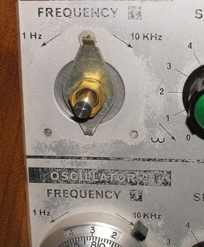
Ten-turn Pots and Dials
The standard Oscillator frequency controls are really cheap, tacky Japanese slow motion vernier drives with an ordinary carbon pot behind.
Apart from looking trash, the backlash is awful and this directly effects the tuning, the knobs move when released after adjusting them!
There is no point in improving the electronics and leaving these controls to ruin it.
To mount replacement precision pots you will need to make an aluminium panel to go behind the Oscillator frequency controls as the slow motion dials have a larger mounting hole size.
- • Firstly, remove the original dials and pots.
- • Cut a strip of 1.5 or 2.0mm aluminium sheet to cover behind the holes and draw a line down the centre.
- • Place behind the panel and align the line so that it is central and going through the small holes above each large hole.
- • Mark through the top and bottom small holes.
- • Remove the strip and centre punch and drill two 3mm holes.
- • Mount the strip behind the panel with two M3 countersunk bolts.
- • Now carefully scribe through the three large hole positions onto the alumimium and remove again.
- • Measure across each circle along the centre line and mark and punch the centre point for the pot mounting positions.
Take care with this to ensure that the pots will be central in each hole. The vertical spacing on a VCS3 is 2.75" (70mm).
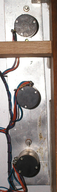
Replace the pots with ten turn wirewound types. I always used a Beckman Model 7246 10k ten turn wirewound type for smooth action and because the wiper tends to stay on the wire.
Other models and makes may leave the element while turning so buy one first to check the action and feel.
The Bi Technologies Model 7286 is one of the few still available, albeit at a jacked up price (Mouser part number 374-7286R10KL.1).
NOTE the pin order, the wiper is often at the end - if you get it wrong you will connect the power rails across the wiper and one end and will melt the wire track!
The Beckman ten turn DUODIAL (46mm diameter) is contemporary and looks in keeping, these are now made by Bi Technologies
(Mouser part number 858-RBC) again at a jacked up price.
They may be called 15 turn types, but the pot prevents more than ten rotations.
There is usually a paper template with the dial for marking the locating lugs. Place these on the aluminium strip and mark and drill the required holes.
Now mount the strip on the front of the VCS3 panel and mark through the locating holes, then drill the VCS3 panel.
This allows the lug of the locating washer to be mounted in front of the panel when the strip is in place behind, as shown in this picture.
Wind the pot fully counter clockwise and the dial to zero and then place the dial on the pot shaft and tighten its grub screw.
Check it rotates smoothly over ten turns without sticking.
The input resistors may need to be increased by 150% because the slow motion pots only use 180 of the 270 degrees of pot rotation.
Sometimes there is a SOT resistor mounted on the pot in series with the pcb one
This may be adjusted to taste: 1 octave per rotation or 10 semitones per rotation.
Precision Patchpins
The standard patchpins contain 2k7 5% resistors and the red "precision" pins contain 2% resistors.
1%, 0.5% and 0.1% resistors are easily obtainable these days and as the resistor errors effect patch repeatability and tracking it is best to replace them.
N.B. Synthi 100 patchpins contain 10k resistors so don't get them mixed!
Only replace with 2k7 if you do NOT intend to implement the recommended matrix buffering modification.
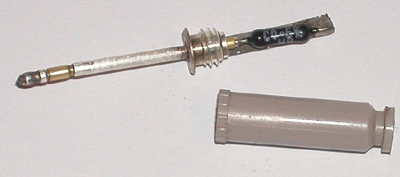
There are at least two designs of pin which are assembled differently.
Some have a cap which unscrews, as shown, others have a pop on cap that has to be pulled off carefully with pliers.
One type has a solid pin and a solder cup inside, the other has a hollow pin.
It's worth checking for solder dry joints and incorrect assembly i.e. the hollow type were sometimes soldered at the top of the tube.
To remove the existing resistor, suck the solder off the top and free from the frame.
Then heat and suck the solder from the pin tip. If the resistor is free pull it out, otherwise reheat and pull out swiftly.
It is important not to leave solder splashes inside the pin tube.
Take the replacement resistor and push one lead right through the pin and solder it at the tip.
Trim the projecting lead and then bend the other lead around the top of the carrier frame.
Check it is straight or the cap will not screw on, then solder.
On the solid types, trim the lead first and solder it in the bucket, then solder the top end.
If your pins look black give them a twist in a rag dampened with contact cleaning fluid.
VCS3 / Synthi A Point by Point Quick Setup Procedure
* RECALIBRATE THE OSCILLATORS AFTER DOING ANY OF THE ABOVE MODIFICATIONS
1. Check Mains voltage setting.
2. Plug in Card A only.
3. PSU Switch on. Adjust PR2 for +12 volts.
4. PSU Adjust PR1 for -9 volts.
5. Plug in Cards B and C.
6. PSU Recheck +12V and -9V.
7. REVERB Adjust Pr3 so that mixing occurs above 2 on the Reverb Mix knob.
8. REVERB Check the voltage control of reverb mix.
9. O/P Adjust PR4 and PR5 for zero residual signals.
10. O/P Check the tracking of Level knobs 4-5-6.
11. ENV Set Trapezoid speed to 65Hz with PR12
12. ENV Set PR13 clockwise.
13. ENV Adjust PR8 for minimum residual signal.
14. ENV Adjust PR13 until signal just reappears, then back off to zero.
15. ENV Check that maximum On time is at least 4 seconds.
16. ENV Check that maximum Decay time is at least 15 seconds.
17. ENV Check that recycling occurs with Off set at 5.
18. ENV Check that recycling does NOT occur with Off set above 7.
19. ENV Check that Trigger functions and does not jam.
20. FILT With filter in oscillation and Frequency control on 5, set PR6 for 261Hz.
21. FILT Check that Response control gives filtering below 5 and oscillation above.
22. FILT Check the shape of the oscillating Sine wave.
23. RM Adjust PR10 for fundamental rejection on A residual signal.
24. RM Adjust PR9 for 1st harmonic rejection on A residual signal.
25. RM Adjust PR11 for fundamental rejection on B residual signal.
26. RM Adjust PR8 for 1st harmonic rejection on B residual signal.
27. RM Check for frequency doubling when both inputs are the same.
28. I/P Check both channels for correct gain on both Hi and Lo inputs.
29. OSC1 Adjust PR17 for best sine wave shape.
30. OSC1 With Frequency on 6 set PR15 for 261Hz.
31. OSC1 With Frequency on 8 add R290 (sot) to achieve 2088Hz.
32. OSC1 Recheck last two steps.
33. OSC1 Check both waveforms.
35. OSC2 Set PR20 half-way.
36. OSC2 Pad shape resistors R227/R228 to achieve correct shapes.
37. OSC2 With Frequency on 6 set PR19 for 261Hz.
38. OSC2 With Frequency on 8 add R291 (sot) to achieve 2088Hz.
39. OSC2 Recheck last two steps.
40. OSC1/2 Adjust PR20 to achieve oscillator tracking to 2kHz.
41. OSC3 Pad shape resistors R261/R262 to achieve correct shapes.
42. OSC3 With Frequency on 8 set PR21 for 63Hz.
43. NOISE Select a (transistor) diode for good bandwidth and level.
44. NOISE Adjust PR2 for around 3 volts p-p noise.
45. NOISE Check the operation of the noise colour control.
46. METER Set signal zero on the meter itself and check operation.
47. METER Adjust PR14 for control voltage zero.
48. JOYSTICK Adjust vertical for equal excursions on meter.
49. JOYSTICK Adjust horizontal for equal excursions on meter.
|